Deploying AKO on vSphere with Tanzu on NSX-T via Supervisor
AKO
on vSphere with Tanzu on NSX-T via SupervisorThis topic explains configuring
Avi Load Balancer
with vSphere using Tanzu deployed with NSX Networking. The focus will be on configuring Avi Load Balancer
components specifically. It assumes that NSX and vSphere are already configured with the requisite functionality. This is for initial Supervisor setup and excludes the installation of Avi Load Balancer
as an L7 ingress controller in Workload clusters.Currently, the following software versions are supported:
Components | Version Supported |
|---|---|
vSphere | 8.0u2 |
NSX | 4.1.1 |
Avi Load Balancer | 22.1.4 |
- Currently,Avi Load Balancersoftware version 30.x is not supported.
- Avi Load Balancerenterprise is required for this installation.
AKO
pod in the Supervisor is deployed as part of Workload Management. The pod consists of two containers, namely AKO-MGR and AKO-INFRA. AKO Infra adds networks to the cloud and IPAM as NCP creates the infrastructure. The troubleshooting steps for the two pods are explained in the later section of this topic.
SE Data segments are DHCP exclusively, making it critical to configure DHCP in the NSX Cloud Connector. The same SE can attach up to nine Data Segments. This means nine namespaces per SE are allowed.
Creating NSX-T cloud
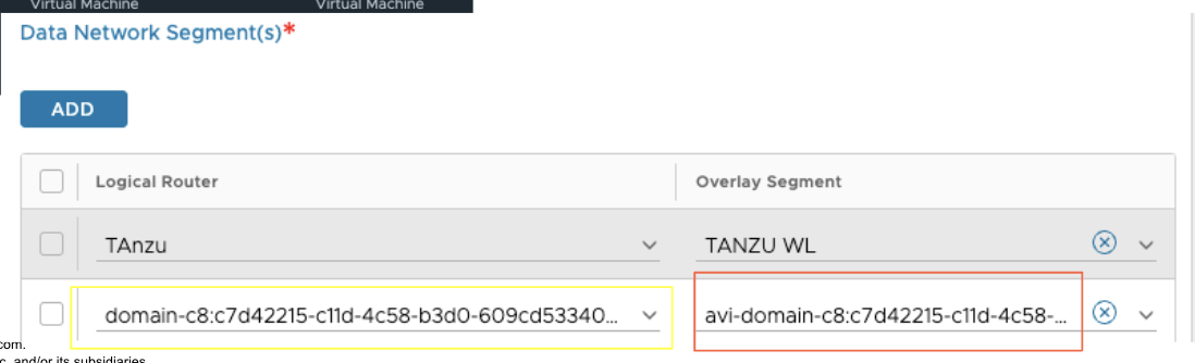
Before creating an NSX-T Cloud, the user must select an existing or create a new segment/vlan-backed network for SE to Controller connectivity. Additionally, the user must create a T1 and overlay segment for data. The data T1 will not be used for the vSphere with Tanzu environment, but it is a mandatory field for the NSX-T cloud creation. To create the cloud, follow these steps:
- Navigate to .
- Enter aNameand anObject Name prefix.
- SelectEnable DHCP. DHCP is used forAvi Load BalancerData segments as shown below:

- UnderNSX, clickCHANGE CREDENTIALSand add theNSX Manager addressand theNSX Manager Credentialsused.
- Once theAvi Load Balancer Controllercan connect to the NSX Manager, select theTransport Zone. It must be the same transport zone used on the VDS switch that you will configure in Workload Manager. It is not supported for multiple clouds to share a Transport Zone.
- Select the T1 (if overlay mode) and segment for AVI MGMT. This network is used for the SE to connect to theAvi Load Balancer Controller.
- Select the T1 (defined earlier) for Data. This T1 will not be used during workload management. It is a mandatory field for cloud creation.
- UndervCenter servers, clickAddto add the vCenter connected to NSX that you intend to use for computing. Currently, one vCenter per NSX cloud for Workload Management is supported.
- In theIPAM Profilefield, select the three dots and clickCreateto create an IPAM profile. Maintain the IPAM profile in its default setting. A blank IPAM profile attached to the cloud is required, andAKOwill use this IPAM.
- ClickSAVE. When the cloud goes green, you can proceed to the next step.
Service Engine Group Selection
The topic does not cover the different SE Group options. However, if you want to modify SEG settings before installing Workload Management, you can modify the Default SE Group for the newly created NSX-T cloud. This SEG is used as a template for the SEG generated for Workload Management.
For more information, see Service Engine Group.
Register Avi Load Balancer with NSX Manager
Avi Load Balancer
with NSX ManagerOnce the cloud is created, the user must register the
Avi Load Balancer Controller
with NSX Manager. This is accomplished with the below API call from NSX-Manager. The call will set the enforcement point on the NSX-Manager so that it will use Avi Load Balancer
as the LB vs NSX LB. It also creates the users that the two AKO
s will use.The user must also change the
Avi Load Balancer
Portal certificate on the Avi Load Balancer Controller
because the default certificate cannot be used. This certificate can be self-signed, signed by a private CA, or a public CA.The certificates must contain the IP addresses of all Controllers and Controller VIP (if present) in the IP SAN field.
Follow the subsequent steps to create a self-signed certificate and change the Portal cert. If you already have a certificate, upload it and its chain to and follow the steps below to change the Portal cert.
Create Self Signed Certificate
- Navigate to .
- Enter theNameof the cert and theCommon Nameof the Controller.
- Add the IP addresses of the Controller and VIP in theSANfield.

- ClickSAVE.
Change Avi Load Balancer Portal Cert
Avi Load Balancer
Portal CertAfter creating the certificate, you can add it as the Portal cert.
- Navigate to .
- UnderAccess, add the new certificate to theSSL/TLS certificatesection as shown below:

- ClickSAVE.
- After uploading the certificate, use the following API call:
 If using NSX 4.1.2 or above, the dns_server or ntp_server fields are not required. Including them will overwrite the settings on theAvi Load Balancer Controller.
 - After executing the API call, and if it is successful, you will receive a response as shown below:

- To verify that NSX has successfully registered withAvi Load Balancer, perform a GET request tohttps://<nsx-mgr-ip>/policy/api/v1/infra/sites/default/enforcement-points/alb-endpoint.The status field must displayDeactivate Provider. If it does,Avi Load Balancerhas been successfully registered as the enforcement point.
- After registering theAvi Load Balancer Controllerwith NSX, you can proceed with the Workload Manager Wizard.
Workload Management Wizard
- Select NSX-T networking from the Wizard and select whether the deployment is three Zones or a Single Cluster. The decision tree for this is outside the scope of this topic.
- Choose the networking options for the management network. This network is for Supervisor management, andAvi Load Balanceris not used for load balancing in any way for this network. The MGMT Network explained here is depicted in the high-level diagram. The network can be another management network or the one on which the infrastructure is deployed on NSX Manager. You must assign five concurrent IP addresses from this network. Three of these will be designated for each Supervisor node, one will serve as a VIP for these nodes, and the remaining IP will be reserved for administrative tasks. Below is an example of a complete configuration:

- After completing the management networking setup, clickNextto the Workload Network page. Below is an example of a complete configuration:
 These fields configure the networking for the Supervisor namespace. A breakdown of the fields is shown below:FieldDescriptionvSphere Distributed SwitchThis is the VDS switch to which the NSX-T Overlay Transport Zone is connected. TheAvi Load Balancer Controllerwill use this switch to define which cloud to use on theAvi Load Balancer Controller.Currently, it is not supported to have multiple clouds on theAvi Load Balancer Controllershare Transport Zone. If so, Workload Manager will select the first cloud with the TZ.Edge ClusterThe Edge Cluster associated with the T0.DNS ServersDNS servers that the nodes will use for DNS.Services CIDRThis is the CIDR used for internal Kubernetes cluster IP services, such as Kube-DNS KUBE-API.Tier 0 gatewayThe T0 is connected to the edge cluster and VDS switch that is in use.Nat ModeIt is a toggle button used when nodes or pods are not routable external to NSX.Namespace NetworkThis network serves as the entire workload network for the namespace. It will be divided into subnets as specified in theNamespace NetworkField. Supervisor Nodes and any workload nodes within the namespace will use this network.Namespace Subnet PrefixA subnet prefix is used to break the Namespace Network up to Cluster Workload Networks.IngressThis network is added to the IPAM on theAvi Load Balancer Controllerand is used for external API and L4/L7 services provided by the Supervisor.The AKO-INFRA pod will configure this network as the IPAM network for NSX-Cloud, incorporating it into the global VRF. IPs will be allocated as /32s and assigned to workload manager T1s as needed. This does not involveAKOproviding L7 ingress. Further details are provided in the later sections.EgressIf NAT mode is toggled, this range will be used as SNAT for external traffic from within the clusters.
 - After completing the fields, selectNextto proceed with the remaining Workload Management configuration. The subsequent steps are not specific toAvi Load Balancerand will not be detailed here.
Ingress Networking

When supervisor or workload clusters are created, NCP builds a T1 for each namespace that connects to the T0 defined above.
A segment is created for Supervisor/Workload node connectivity. This subnet is drawn from the Namespace Network and is sized according to the Namespace Subnet Prefix. For instance, if the Namespace Network is 10.244.0.0/21 and the Namespace Subnet Prefix is /28, the initial Workload segment for the supervisor would be 10.244.0.0/28.
NCP also creates a segment on the same T1 for
Avi Load Balancer
to use for data connectivity. This segment, which is non-routable externally, is sourced from the CGNAT range and has DHCP enabled.When NCP creates the segment, it instructs the AKO-INFRA pod to add the namespace T1 and the newly created Data Segment to the NSX-T cloud. The
Avi Load Balancer
SE then sends a DHCP request to NSX-T to receive an IP address/gateway, and default route, enabling it to configure its NIC for the segment.This highlights the importance of having DHCP enabled on the cloud, as previously mentioned.
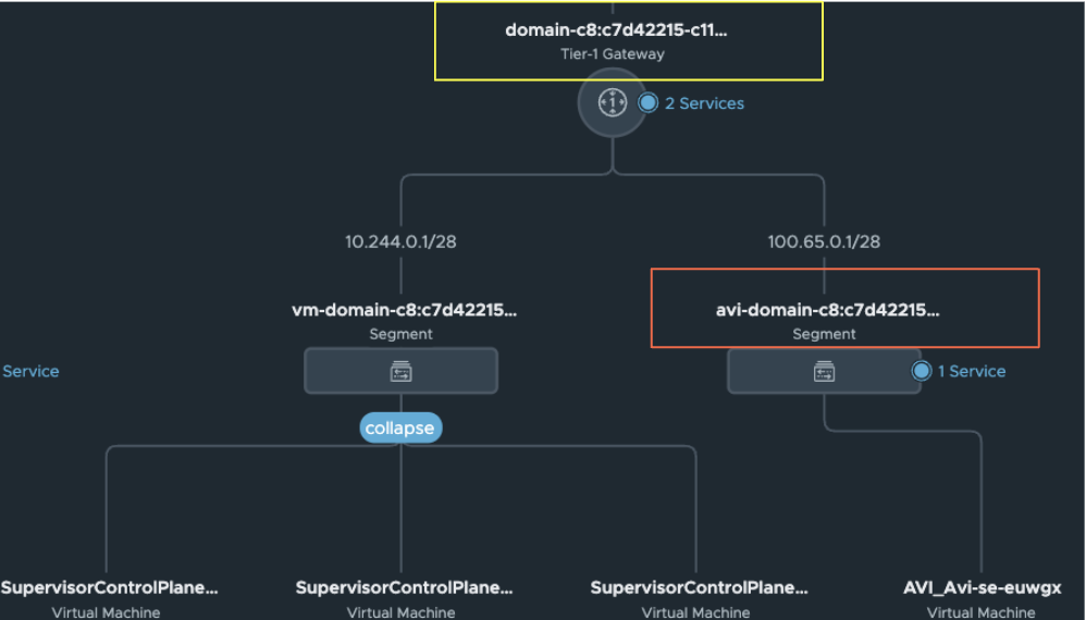
The NSX-T Cloud will display the T1 and Data Segment as shown below:
After AKO-Infra adds the segment to the cloud, it uses one of the IPs from the ingress field above, such as 192.168.68.240/28, as the actual VIP. The
Avi Load Balancer Controller
, through the cloud connector and NSX Manager, then adds the static routing for the T1 and advertises the network to the T0 and beyond.Once created, the NSX-T Topology must appear similar to the example shown below:
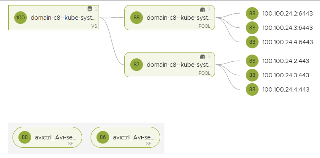
Once Workload Manager completes, you should see the Virtual Service for Kube API for the supervisor.
Troubleshooting
If the installation process is stalled and you need to troubleshoot the
AKO
pods, perform the following steps:- SSH as root to vCenter running the sup cluster.
- Run the following script as root./usr/lib/vmware-wcp/decryptK8Pwd.py
- This will provide the IP address for the management side of the Supervisor and the password as shown below:

- SSH into the supervisor with the above credentials, and you can runkubectlcommands against the supervisor.
- TheAKOpod is deployed in thevmware-system-akonamespace. To view the logs for theAKOinfra pod, use the following command:Kubectl logs vmware-system-ako-ako-controller-xxxxxx -n vmware-system-ako -c infraThis will show if there are any errors on theAKOside.